1. Map the Control Points First
Before selecting anything, identify every damper point in the system. A typical large ventilation installation includes:
| Control point | Role |
|---|---|
| Fresh-air damper | Brings outdoor air into the AHU |
| Return-air damper | Recirculates indoor air |
| Exhaust damper | Removes stale air to outside |
| Mixing-box dampers | Blend fresh, return, and exhaust air |
| VAV box dampers | Regulate airflow to each zone |
| Bypass dampers | Bypass coils or balance system pressure |
| Fire/smoke dampers | Isolate ducts in an emergency |
Each point has a different job, and therefore a different actuator configuration. The complete system is only as good as the weakest damper point.
2. Size the Actuator: Torque Is the Foundation
The single most important selection parameter for a damper actuator is torque - the rotational force needed to move the damper blade against air pressure.
The basic calculation:
Required torque = Damper area × torque factor × safety factor
Damper area:
Rectangular damper: length × width
Round damper: π × r²
Torque factor:
A widely used rule of thumb is that 1 square meter of damper requires roughly 4-6 Nm of torque. For airtight applications or high-velocity ducts (face velocity above ~12 m/s or static pressure around 500 Pa), the load factor rises to about 12 Nm per m².
Safety factor:
Always add a safety margin of 25-50% to account for aging dampers, blade friction, and dust build-up.
A worked example:
A rectangular fresh-air damper measures 1.0 m × 1.5 m = 1.5 m².
Base torque: 1.5 m² × 5 Nm/m² ≈ 7.5 Nm
With 50% safety factor: ≈ 11.3 Nm
The correct choice would be the next actuator size up - a 15 Nm unit.
The golden rule from experienced engineers: always select an actuator whose rated torque exceeds the calculated requirement, and when in doubt, choose the next larger size.
3. Match Actuator Torque Ranges to Damper Sizes
Different torque ranges serve different damper sizes. A practical guide:
| Actuator torque | Typical damper area |
|---|---|
| 3 Nm | Small dampers up to ~0.5 m² |
| 5 Nm | Dampers up to ~1.5 m² |
| 10 Nm | Dampers up to ~1.5-2 m² |
| 15 Nm | Dampers up to ~3 m² |
| 20 Nm | Large dampers up to ~4 m² |
| 20-40 Nm | Very large / high-pressure dampers |
For very large dampers, the configuration may require multiple actuators linked across blade sections, or a single high-torque industrial actuator.
4. Choose the Control Type
Not every damper point needs the same control behavior:
On/Off (two-position) control
Damper drives to fully open or fully closed only
Best for: fresh-air isolation, exhaust, fire/smoke, simple zone switching
Simple wiring, lower cost
Modulating (proportional) control
Damper positions anywhere between open and closed via a continuous signal
Standard signals: 0-10V DC or 4-20mA
Best for: VAV boxes, mixing boxes, and precise airflow regulation
Provides feedback for real-time position monitoring
For a large ventilation system, you will typically use both - modulating actuators on VAV and mixing points, on/off actuators on isolation and safety points.
5. Configure Fail-Safe Behavior
Large ventilation systems have strict safety requirements, so fail-safe configuration matters more than in small systems.
Spring-return actuators contain an internal spring that automatically drives the damper to a safe position on power loss:
Fail-closed - for fresh-air isolation and freeze protection
Fail-open - for smoke-exhaust applications
The spring return is typically fast (e.g. under 25-30 seconds), even when the motorized travel is slower
Non-spring-return actuators hold their last position on power loss - acceptable for non-critical modulating points, but not for safety-critical dampers.
6. Configure Power and Wiring
Power supply selection shapes the whole installation:
| Option | Use case |
|---|---|
| AC/DC 24V | Safe low-voltage control, common with BMS/DDC controllers; Class III installations |
| AC 100-240V | Direct mains-powered actuators, simpler in retrofit projects; Class II double-insulated |
In multi-zone systems, always size the transformer with headroom - plan for all actuators operating simultaneously, and follow the guidance that each actuator needs adequate VA reserve (a common rule of thumb is at least 7VA per actuator, plus margin for wire resistance). Run control signal wiring separately from power wiring to avoid interference.
7. Configure Accessories and Integration
A complete configuration also covers the details:
Auxiliary switches - dry contacts (e.g. 2× SPDT) for interlocking with fans, alarms, or BMS status
Position feedback - analog feedback signal for modulating points
Mechanical position indicator - for on-site visual checks
Manual override - allows unpowered manual positioning during commissioning
Shaft compatibility - match the actuator coupling to the damper shaft size (round or square)
IP rating - IP54 for dust and water-splash protection in mechanical rooms
8. The Complete Configuration Checklist
Before ordering, run through this checklist:
□ Every damper point mapped (fresh air, return, exhaust, VAV, fire/smoke, bypass)
□ Damper area calculated for each point
□ Torque calculated with safety factor (25-50%)
□ Actuator torque exceeds requirement - next size up when in doubt
□ Control type matched: on/off or modulating (0-10V / 4-20mA)
□ Fail-safe behavior configured: spring-return, fail-closed or fail-open
□ Power supply and transformer sized with headroom
□ Auxiliary switches, feedback, and manual override specified
□ Shaft and mounting compatibility verified
□ IP rating and temperature range suitable for the environment
9. Hysen: A Complete Actuator Range for Large Ventilation
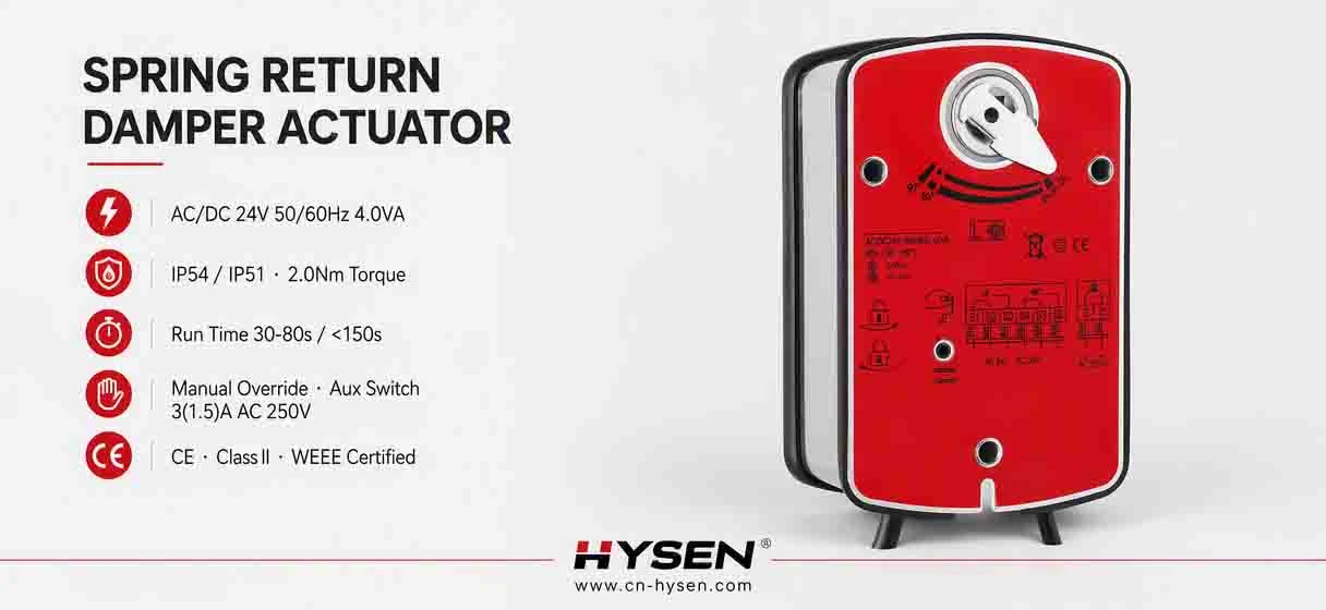
At Hysen, we supply the full actuator range you need to configure large ventilation systems - from modulating VAV drives to high-torque spring-return units for big dampers.
Modulating control:
HY-DMS05-24(S) - 5Nm modulating actuator, AC/DC 24V, 0(2)-10V / 0(4)-20mA control and feedback, spring return <20s, IP54, for dampers up to 1.5 m².
High-torque spring-return on/off:
| Model | Torque | Damper area | Power | Motorized / spring reset |
|---|---|---|---|---|
| HY-DFS10-230(S) | 10 Nm | up to 1.5 m² | AC 100-240V | <100s / <25s |
| HY-DFS15-230(S) | 15 Nm | up to 3 m² | AC 100-240V | <150s / <25s |
| HY-DFS20-230(S) | 20 Nm | up to 4 m² | AC 100-240V | <180s / <30s |
The DFS series features universal AC 100-240V (85-265V tolerance) input, fail-safe spring return, manual override, up to 95° adjustable rotation, IP54 protection, Class II double insulation, and optional 2× SPDT auxiliary switches - ideal for AHUs, central ventilation, industrial ducts, and fire & safety ventilation.
All Hysen actuators and motorized valves integrate with BMS/BAS systems and are available with OEM/ODM customization to match your project exactly.
10. The Takeaway
A complete valve-and-actuator configuration for large ventilation systems is built on five decisions: map every damper point, size the torque with margin, choose the right control type, configure fail-safe behavior, and plan the power and wiring. Get these right, and the system installs cleanly, operates efficiently, and stays reliable for years.
If you are configuring actuators for a ventilation project - from a single AHU to a full building - the Hysen team can help you size every point correctly.
Contact Hysen today for a configuration consultation, samples, and OEM/ODM support.