

HVAC Air Duct Motorised Damper Actuators
Author: [2026-10-02] | By Xiamen Hysen Control Technology Co., Ltd. Sally Chen sally@cn-hysen.com
An HVAC air duct damper actuator converts an electrical control signal into mechanical damper movement. For commercial ventilation, the selection normally comes down to torque, supply voltage, control mode, fail position, running time, and environmental/fire requirements rather than actuator appearance. Hysen supplies motorised damper actuators from 2 Nm to 40 Nm, with 24 V and 230 V options for on/off, 3-point and modulating control.
For OEM projects, the actuator must also match the damper shaft, blade loading, required rotation angle, installation space, control panel output and the system's safety sequence.
2–40 Nm HVAC Damper Actuator Selection: What Engineers Check First
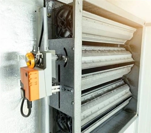
A damper actuator is the final mechanical element between the building automation system and the air damper. The actuator receives an electrical command and generates rotary torque at the output shaft.
The basic selection parameters are:
- 2–40 Nm rated torque for different damper sizes and mechanical loads.
- 24 V or 230 V power supply according to the control cabinet architecture.
- 2-point, 3-point or modulating control depending on the HVAC control strategy.
- Non-fail-safe or spring-return operation according to the required power-loss position.
- Open/close or proportional positioning for volume control and air mixing.
- Direct damper-shaft mounting for field installation.
- Standard, quick-running, low-noise, fire-smoke and explosion-proof configurations for different operating environments.
24 V vs 230 V HVAC Actuator Electrical Selection
The supply voltage should be selected together with the controller, transformer capacity, cable length and installation environment.
| Parameter | 24 V Actuator | 230 V Actuator |
|---|---|---|
| Nominal supply | 24 VAC/DC depending on model | 230 VAC |
| Typical application | BMS, AHU, FCU and control panels | Direct building power applications |
| Control cabinet requirement | Usually requires 24 V supply/transformer | Mains-rated output required |
| Cable safety | SELV architecture possible depending on system design | Mains-voltage wiring |
| Commissioning | Low-voltage control environment | Electrical isolation and mains procedures required |
| Typical selection driver | BMS integration | Direct mains-powered HVAC equipment |
For an OEM controller, the actuator voltage should be fixed before the PCB relay, terminal block, fuse and enclosure design are finalized. A 24 V actuator should not simply be substituted with a 230 V model because the control signal may remain electrically incompatible.
2–40 Nm Torque: Why Damper Size Alone Is Not Enough
Torque is determined by the damper's mechanical resistance, blade geometry, shaft condition, seal friction, air pressure differential and linkage arrangement.
A larger damper does not automatically mean a specific actuator torque. Engineers should measure or obtain the manufacturer's required shaft torque and then select an actuator with sufficient operating margin.
| Selection Parameter | Engineering Consideration |
|---|---|
| 2–10 Nm | Small and medium HVAC dampers |
| 10–20 Nm | Medium-load ventilation applications |
| 20–40 Nm | Larger or higher-resistance dampers |
| Damper shaft | Must match actuator clamp/adapter |
| Rotation | Common quarter-turn applications |
| Load | Include blade friction and system pressure effects |
| Safety margin | Select according to actual damper manufacturer's torque data |
An undersized actuator can stall, overheat or fail to achieve the commanded damper position. An unnecessarily oversized actuator increases cost, installation space and mechanical loading.
Request an HVAC Actuator Solution
2-Point, 3-Point and Modulating Control: Electrical Logic
The control method determines how the actuator receives its command from a thermostat, AHU controller, PLC or building management system.
2-Point On/Off Control for 24 V and 230 V HVAC Systems
With 2-point control, the actuator receives a command to drive toward one end position or the other.
This architecture is common for:
- Fresh-air dampers.
- Return-air isolation dampers.
- Exhaust-air dampers.
- Fan start/stop sequences.
- Simple ventilation zones.
- Equipment isolation.
The control circuit should account for the actuator's rated voltage and switching requirements. A controller designed for a 24 V actuator should not directly switch a 230 V actuator unless the output stage is specifically designed and safety-rated for mains switching.
3-Point Floating Control for HVAC Damper Positioning
A 3-point actuator normally uses separate control commands for open, close and a common connection.
The controller determines the actuator direction by energizing the corresponding input. Removing both commands stops movement, depending on the actuator architecture.
This arrangement is useful when the controller needs intermediate damper positions without using a dedicated analog signal.
Modulating Control with 0–10 V HVAC Control Signals
Modulating actuators are used when the HVAC controller needs continuous damper positioning rather than only open/closed operation.
Typical control architectures include:
- 0–10 V command.
- 2–10 V command.
- Analog feedback.
- Dedicated proportional controller outputs.
For AHU fresh-air and return-air mixing, proportional positioning allows the control system to adjust the ratio between fresh air and return air instead of repeatedly driving the damper between two end positions.
2–40 Nm Standard Non-Fail-Safe Actuators for General HVAC Dampers
A standard damper actuator, also called a non-fail-safe damper actuator, continues to hold or operate according to its motor/control architecture when power is available.
Hysen standard models cover a 2 Nm to 40 Nm torque range, allowing the same actuator family to be applied across multiple damper dimensions.
Typical applications include:
- AHU fresh-air dampers.
- Return-air dampers.
- Exhaust dampers.
- Air mixing dampers.
- Zone ventilation dampers.
- General commercial HVAC systems.
The main engineering advantage of a standard actuator is straightforward installation where a defined power-loss safety position is not required.
For an OEM project, the actuator housing, shaft adapter, cable entry, rotation angle and terminal arrangement should be fixed before tooling and enclosure design.
24 V/230 V Standard Actuator Integration
For a controller manufacturer, the actuator interface should be defined in the electrical specification.
| Parameter | Specification to Confirm |
|---|---|
| Supply voltage | 24 V or 230 V |
| Control type | 2-point / 3-point / modulating |
| Torque | 2–40 Nm |
| Rotation | Damper-specific |
| Feedback | Required or not required |
| Shaft adapter | Match damper shaft |
| Installation | Direct shaft mounting |
| Enclosure | Required IP rating according to application |
| Operating temperature | Confirm against project environment |
Spring-Return Fail-Safe Actuators for Power-Loss Protection
A spring-return damper actuator uses motorized operation during normal power conditions and a mechanical spring to drive the damper to a defined fail position after power interruption.
This is fundamentally different from a standard non-fail-safe actuator.
The fail position must be defined at the system-design stage. Depending on the HVAC and fire-control sequence, the required position may be fully open or fully closed.
Spring-Return Operation During 24 V and 230 V Power Failure
The operating sequence can be simplified as:
- Electrical power is applied.
- The actuator motor moves the damper to the commanded position.
- The spring is mechanically loaded.
- Power is interrupted.
- The stored spring energy drives the actuator toward its fail position.
- The damper reaches the predefined safety position.
This mechanism is particularly relevant to ventilation systems where damper position during a power failure has a direct effect on smoke control, equipment protection or air isolation.
Fail-Safe vs Non-Fail-Safe HVAC Actuators
| Parameter | Non-Fail-Safe Actuator | Spring-Return Actuator |
|---|---|---|
| Power failure | No spring-driven return | Mechanical return |
| Fail position | Not inherently defined by spring | Open or closed according to design |
| Main application | General HVAC | Safety-related ventilation sequences |
| Mechanical element | Motor/gear train | Motor + spring mechanism |
| Selection factor | Normal operating torque | Operating torque + spring-return requirement |
Request a Spring-Return Actuator Specification
Fire-Smoke Damper Actuators at 280°C: Safety Sequence and Selection
Fire-smoke damper actuators are designed for applications where the actuator and damper form part of a smoke-control or fire-isolation system.
The supplied application specification identifies a 280°C smoke exhaust pipe temperature trigger for the fire emergency sequence. The exact thermal trip temperature, damper rating and actuator certification must always be matched to the applicable local fire code and the complete damper assembly.
A fire-smoke actuator should therefore not be selected solely from its torque rating.
280°C Fire Sequence and Spring-Return Operation
A typical sequence can involve:
- Normal HVAC operation with the damper motorized to its required position.
- Fire or smoke detection initiating the emergency control sequence.
- Thermal sensing or an external safety circuit interrupting normal actuator operation.
- Spring-return movement toward the designated safety position.
- Damper isolation or smoke-control operation according to the engineered fire strategy.
The actuator, thermal release device, damper, control panel and fire detection system must operate as one coordinated safety chain.
Fire-Smoke Actuator Selection Parameters
| Parameter | Engineering Requirement |
|---|---|
| Application | Fire/smoke damper |
| Normal operation | Motorized damper movement |
| Emergency operation | Spring-return or specified safety action |
| Thermal condition | Application may involve 280°C trigger specification |
| Power | 24 V or 230 V according to model/system |
| Torque | Selected according to damper resistance |
| Control | On/off or application-specific control |
| Certification | Must match the required fire/smoke assembly standard |
The certification of the complete fire-rated damper assembly should not be inferred from the presence of a fire-smoke actuator alone.
Quick-Running HVAC Actuators for Fast Airflow Sequences
A quick-running damper actuator is selected when the damper must reach its commanded position faster than a conventional actuator.
This can matter in laboratories, pressure-controlled spaces, ventilation equipment and systems where damper position changes are part of a fast operating sequence.
Fast-Running 24 V and 230 V Damper Control
The important parameters are not only torque and supply voltage. Engineers should also verify:
- Opening time.
- Closing time.
- Damper rotation angle.
- Maximum operating cycles.
- Motor temperature rise.
- Control output switching frequency.
- Mechanical stop arrangement.
- Required position feedback.
A faster actuator can also create greater mechanical acceleration at the damper shaft. The damper linkage and shaft assembly therefore need to tolerate the resulting dynamic load.
Low-Noise HVAC Damper Actuators for Offices and Hospitals
Low-noise actuators are intended for applications where motor and gear noise can affect the occupied environment.
Typical installations include:
- Office buildings.
- Hotels.
- Hospitals.
- Residential HVAC systems.
- Meeting rooms.
- Libraries.
- Other noise-sensitive spaces.
Low-Noise Actuator Design at Mechanical Gear Level
The acoustic output of an actuator is affected by motor type, gear reduction, mechanical tolerances, mounting rigidity and damper load.
A low-noise specification should therefore identify an actual measured sound level and test condition rather than rely only on the term "quiet."
For OEM procurement, request the following test information:
| Test Item | Data Required |
|---|---|
| Sound pressure level | dB(A) |
| Test distance | Defined measurement distance |
| Operating condition | No-load or rated-load |
| Supply voltage | Test voltage |
| Rotation | Opening/closing |
| Mounting | Test fixture or installed damper |
| Ambient condition | Temperature and room condition |
Explosion-Proof Damper Actuators for ATEX Zones 1/2 and 21/22
Explosion-proof actuators are used where the surrounding atmosphere may contain combustible gases, vapors, mists or dust.
The supplied application range includes:
- Gas and mist: Zones 1 and 2.
- Dust: Zones 21 and 22.
- Air dampers.
- Fire and smoke dampers.
- Volume-control dampers.
- Ball valves.
- Throttle valves.
- Quarter-turn valves.
ATEX Zone 1/2 and 21/22 Actuator Selection
Zone classification determines the required equipment protection concept. The actuator must be selected according to the hazardous-area classification, gas/dust group, temperature class and applicable certification.
| Hazardous Area | Atmosphere | Typical Zone Classification |
|---|---|---|
| Gas/vapor/mist | Explosive atmosphere may occur during normal operation | Zone 1 |
| Gas/vapor/mist | Explosive atmosphere unlikely during normal operation | Zone 2 |
| Combustible dust | Explosive dust atmosphere may occur during normal operation | Zone 21 |
| Combustible dust | Explosive dust atmosphere unlikely during normal operation | Zone 22 |
The actuator certification must correspond to the actual installation zone. A conventional HVAC actuator must not be treated as explosion-proof simply because it operates a damper in an industrial building.
AHU Fresh-Air and Return-Air Dampers: 24 V Control Sequence
Air handling units commonly use multiple dampers to control fresh air, return air and exhaust air.
A simplified mixing-air arrangement contains:
Fresh air → Fresh-air damper → Mixing chamber → Supply fan → Building
while return air is routed back toward the mixing section through a separate return-air damper.
The actuator position can be controlled according to:
- Indoor air quality.
- Outdoor air temperature.
- Fan operating state.
- Cooling demand.
- Heating demand.
- Freeze protection.
- Smoke-control sequence.
- Minimum fresh-air requirements.
Low-Temperature Alarm and Damper Shutdown Logic
The actuator can form part of a low-temperature protection sequence.
For example:
- AHU starts.
- Fresh-air damper opens to its commanded minimum position.
- Fan operates.
- Temperature sensor monitors the coil/air path.
- Low-temperature alarm is detected.
- Controller removes the normal damper command or issues the configured safety command.
- Fresh-air damper moves toward the specified protective position.
- Heating and fan control follow the programmed sequence.
The exact fail position depends on the AHU design and freeze-protection strategy.
24 V/230 V OEM Procurement Checklist for HVAC Actuator Projects
For an HVAC actuator factory order, a purchase specification should contain more than "24 V damper actuator, 10 Nm."
A technically useful RFQ should specify:
Electrical Parameters: 24 V/230 V and Control Type
- Rated voltage.
- AC/DC requirement.
- Frequency.
- 2-point, 3-point or modulating control.
- Input signal range.
- Feedback signal requirement.
- Maximum control current.
- Terminal configuration.
- Cable length.
- Connector type.
Mechanical Parameters: 2–40 Nm and Damper Interface
- Rated torque.
- Minimum required torque.
- Shaft diameter.
- Shaft shape.
- Clamp type.
- Rotation angle.
- Manual override requirement.
- Damper mounting orientation.
- Mechanical end stops.
- Required running time.
Environmental Parameters: IP Rating and Temperature
- Ambient operating temperature.
- Storage temperature.
- Relative humidity.
- Enclosure/IP requirement.
- UV exposure.
- Condensation.
- Corrosive atmosphere.
- Indoor/outdoor installation.
Compliance Parameters: CE-LVD, EMC and Safety
Depending on the target market and product architecture, the technical file may need to address requirements associated with:
- CE-LVD
- EMC
- RoHS
- REACH
- UL 60730
- FCC Part 15
Applicable fire/smoke requirements
Applicable hazardous-area certification for explosion-proof models
The applicable standard depends on the exact actuator construction, market and intended use. Certification claims should be made against the specific model rather than against the entire product family without verification.
2–40 Nm HVAC Damper Actuator Factory Production and Testing
For a China HVAC damper actuator manufacturer, quality control needs to cover both the electrical drive system and mechanical transmission.
A production inspection plan can include:
| Test | Purpose |
|---|---|
| Input voltage test | Verify electrical operating range |
| Current consumption | Detect motor/electrical abnormalities |
| Torque test | Confirm output torque |
| Direction test | Verify open/close logic |
| Running-time test | Confirm actuator speed |
| End-stop test | Verify travel limitation |
| Power-loss test | Verify spring-return operation where applicable |
| Noise test | Confirm low-noise model performance |
| Insulation test | Check electrical insulation |
| Dielectric strength | Verify insulation withstand |
| Functional cycling | Detect mechanical wear or gear defects |
| Visual inspection | Check housing, terminals and assembly |
Burn-In Testing for Motor and Gear Assembly
Burn-in testing can expose early failures caused by motor winding defects, gear engagement problems, incorrect lubrication, terminal faults or PCB assembly errors.
For production projects, the test duration and operating cycle should be defined in the quality agreement rather than using an unspecified "aging test."
HVAC Damper Actuator Application Matrix: 2–40 Nm
| Application | Recommended Actuator Type | Typical Control | Key Selection Factor |
|---|---|---|---|
| General AHU damper | Standard | 2-point/3-point/modulating | Torque and shaft fit |
| Fresh-air damper | Standard / spring-return | 2-point/modulating | Minimum fresh-air position |
| Return-air damper | Standard / modulating | 3-point/0–10 V | Air mixing ratio |
| Exhaust damper | Standard / spring-return | On/off | Fail position |
| Smoke damper | Fire-smoke | Safety sequence | Fire/smoke certification |
| Laboratory ventilation | Quick-running | On/off/modulating | Running time |
| Hospital ventilation | Low-noise | Modulating | Acoustic performance |
| Hazardous-area ventilation | Explosion-proof | Application-specific | ATEX zone/certification |
| Large damper | Higher-torque model | Modulating/on/off | Shaft torque |
| Compact damper | Standard actuator | 2-point/3-point | Installation space |
Why HVAC Damper Actuator Torque, Voltage and Fail Position Must Be Specified Together
Three specifications frequently appear separately in procurement documents but should be treated as one actuator-selection problem:
- Torque determines whether the actuator can move the damper.
- Voltage determines whether the control system can safely power it.
- Fail position determines what the ventilation system does after loss of power or a safety trip.
For example, a 10 Nm, 24 V, spring-return actuator and a 10 Nm, 230 V, non-fail-safe actuator have the same nominal torque but are not interchangeable products.
For OEM customers, this distinction is particularly important because the actuator specification affects:
- Controller PCB output design.
- Transformer sizing.
- Relay selection.
- Terminal block configuration.
- Enclosure dimensions.
- Cable specification.
- Software/control logic.
- Safety documentation.
- Product certification.
Hysen develops and supplies different HVAC damper actuator configurations for ventilation, AHU, fire/smoke, fast-running, low-noise and hazardous-area applications. For OEM and project procurement, the correct model should be selected from the actual damper torque, control architecture and installation conditions.
Request OEM HVAC Damper Actuator Pricing
Frequently Asked Questions: 24 V, 2–40 Nm and OEM Damper Actuators
How do I calculate the required torque for an HVAC damper actuator?
Obtain the damper manufacturer's required shaft torque under actual operating pressure, then select an actuator with suitable torque margin. Do not select torque from damper dimensions alone.
Should I choose a 24 V or 230 V HVAC damper actuator?
Choose the voltage that matches the controller output and electrical architecture. 24 V is common for BMS and control-panel systems, while 230 V suits directly mains-powered HVAC equipment.
Can a standard HVAC damper actuator replace a spring-return actuator?
Not where the system requires automatic movement to a defined position after power loss. A spring-return actuator provides mechanical fail-safe movement; a standard actuator does not provide the same spring-driven function.


